SALES@TAPESWITCH.COM


Principle of Safety
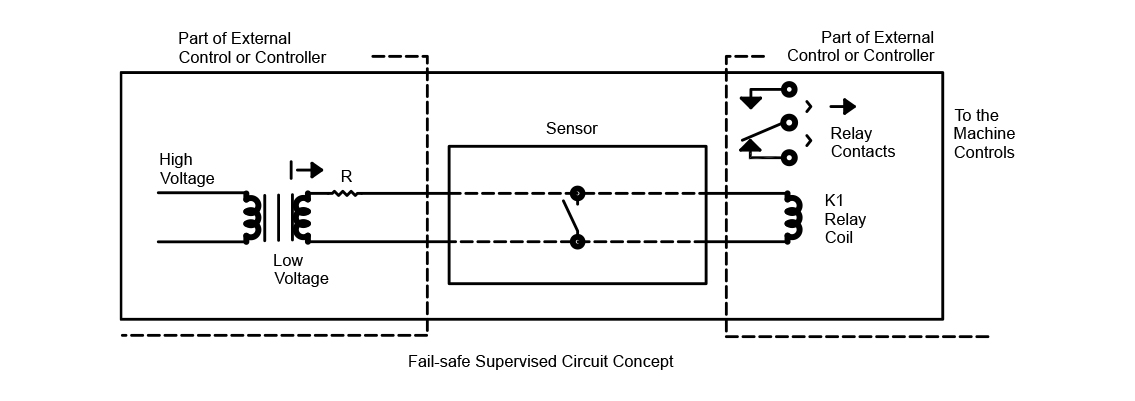
The fail-safe concept monitors the sensor status at all times. In the event of a failure, the fail-safe concept will simulate a protected position. The “protected” position is when the sensor is activated (closed) and the “normal” or “run” position is when the sensor is not activated (open).
• Normal Conditions – constant current flow (I) holding relay coil (K1) energized
• Loss of Power – no current flow (I) and relay coil (K1) is de-energized
• Actuation of Sensor – relay coil (K1) is shorted and de-energized
• Failure of Sensor in the closed position – relay coil (K1) is shorted and de-energize
• Failure of Sensor in the open position – (broken wire, switch or conductor) interupts current flow (I) and relay coil (K1) is de-energized
• Resistor R – limits current flow through the sensor when actuated
Fail-Safe (4 wire system)
Fail-Safe is a shorthand term used to mean Fail to a Safe condition. In machinery with known hazards, the system is Fail-Safe when any failure leaves the machinery in a safe condition. The 4-wire fail-safe concept is illustrated in the figure above. A small current is constantly flowing through the sensor at all times, holding the relay coil energized at all times. The machine controls, interrupt, or stop circuitry is connected to the contacts of this relay. If the sensor is actuated, the relay coil will be shorted, causing the relay to deenergize. A resistor in series provides current limiting from overdrawing the power supply and limits the current through the sensor in the actuated position. If the sensor fails in the closed position the relay will be shorted and cannot be energized until the failure is corrected. If the sensor fails in the open position, the current path for the relay coil no longer exists and the relay coil cannot be energized until the current path is restored and the failure corrected.
In addition to the safety aspects achieved with Fail-Safe, it also provides:
• Isolation of the machine controls and sensor(s)
• Isolation of high amperage and high voltage machine switching from the low voltage sensors
• Conversion of a normally-open switch to required normally closed machine controls